

How to Select a Linear Guide Based on Load and Moment: Calculation Guide
How to Select a Linear Guide Based on Load and Overturning Moment: Types of Loads, the L10 Life Concept, and a Step-by-Step Method for Sizing Without Over- or Under-Specifying.
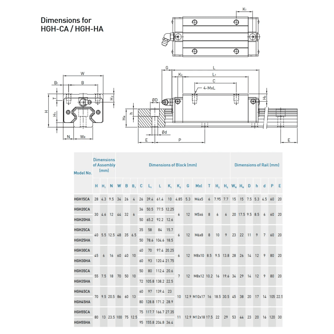
The most costly mistake when selecting a linear guide is sizing it incorrectly: an undersized guide fails prematurely, and an oversized one wastes budget. Calculating based on load and moment is what distinguishes a professional selection from a guess. You don’t need to be a design engineer, but you do need to understand what is being measured and why. Here we explain the types of loads acting on a guide, the concept of service life, and the method for proper sizing.
The types of loads acting on a guide
A single force does not act on a carriage. The following must be considered: the radial load (perpendicular to the guide, downward, typically the weight); the reverse radial load (upward, in inverted mountings or when process forces are present); the lateral load (from the side); and the pitch, yaw, and roll moments, which occur when the load is not centered on the carriage. A good profile guide, thanks to its Gothic arch design, withstands forces in all three directions and all three moments.
The most overlooked factor
When the load extends beyond the carriage (cantilevered) or is raised above it, it generates a moment a rotational force that can be much more demanding than the weight itself. Ignoring the overturning moment is the most common cause of undersizing: the guide “supports the weight” but fails due to the moment. That is why the position of the load relative to the carriage is just as important as its magnitude.
Load capacity: C and C0
The catalogs provide two key values for each model: the dynamic load capacity (C), which is used to calculate the service life while the system is in motion; and the static load capacity (C0), which is the limit when the system is at rest or under impact. The actual load in your application should remain well below these values, taking a safety factor into account.
L10 service life
The nominal life L10 is the distance (in km) that 90% of the guides of a given model travel before showing signs of fatigue under nominal conditions. It is calculated based on the ratio of the dynamic capacity (C) to the actual applied load (P): the higher this ratio, the longer the life. The relationship is not linear; even small increases in load significantly reduce service life, so allowing for a margin is key. This is the same principle that governs the service life of bearings.
The Step-by-Step Selection Method
Step 1: Identify all loads and their positions relative to the carriage (weight, process forces, overhang). Step 2: Calculate the equivalent load by combining forces and moments. Step 3: Apply the safety factor based on the type of service (higher if there is impact or vibration). Step 4: Compare with the (static) capacity C0 and calculate the service life L10 using C. Step 5: If the service life is insufficient, increase the size, switch to rollers, or add more carriages. Step 6: Define the preload and precision based on the required stiffness and accuracy.
How to Distribute the Load Among Several Carts
A key strategy: Using two or more trolleys per rail, or two parallel rails, distributes the load and reduces the moment on each trolley. Increasing the spacing between trolleys reduces the effect of the overturning moment. Often, rather than upgrading to a larger size, the most cost-effective solution is to add a trolley or increase the spacing between existing ones.
When to Ask for Support
Detailed calculations involving combined moments and variable load profiles can become complex. For critical applications, it is advisable to rely on the manufacturer’s selection software or seek technical advice. At BIOSA, we use the HIWIN method to size your guide at no cost, avoiding both undersizing and unnecessary expenses.
Selecting based on load and moment is what turns choosing a guide into an engineering decision rather than a guessing game. Considering all loads, the overturning moment, the C and C0 ratings, and the L10 life, and distributing the load across multiple carriages when appropriate prevents early failures and cost overruns. At BIOSA MOTION TECHNOLOGIES, we size your HIWIN guide using the manufacturer’s method, at no cost. To see the types available, check out our guide to linear guide types.