

Parts of a Gearmotor: Complete Anatomy
Before selecting, installing, or maintaining a gearmotor, it is important to identify each of its parts and the function it performs.
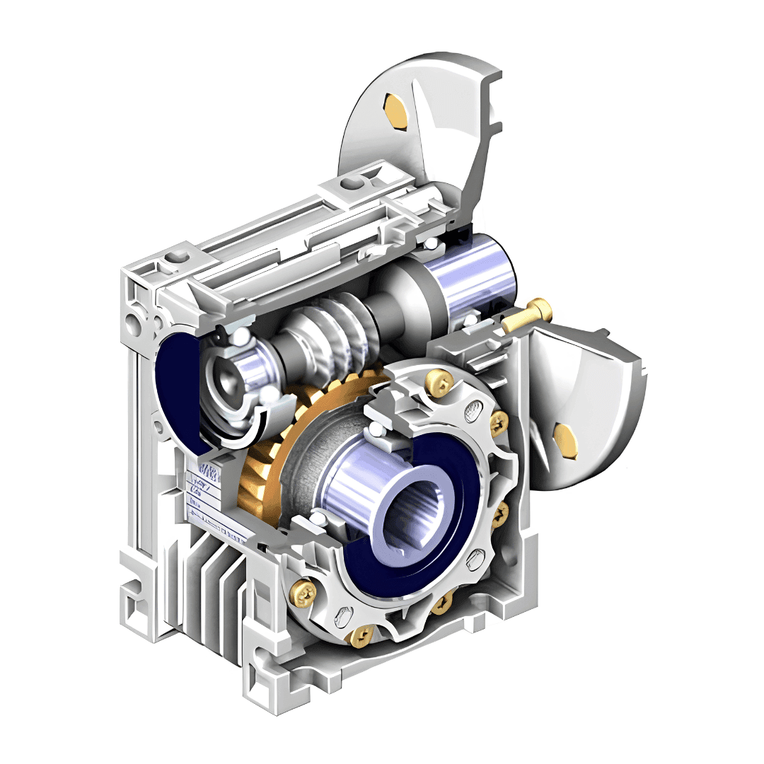
Housing
The housing contains the internal gears and lubricant, and defines the mounting position of the gearmotor. It can be manufactured from cast aluminum, which is lighter and provides better heat dissipation, or cast iron, which is more robust for larger sizes or frequent shock loads.
Gear Train
It is the set of components responsible for speed reduction. Depending on the type of reducer, it can be a worm screw and worm wheel (NMRV series), a set of spur or helical gears (parallel shaft or inline reducers), or bevel gears (right-angle reducers).
Input Shaft and Output Shaft
Input shaft: Receives the rotation from the motor, either integrated into a gearmotor or externally coupled in a separate reducer. Output shaft: Delivers the reduced rotation and multiplied torque to the driven equipment. It can be a solid shaft or hollow shaft depending on the design.
Seals and Bearings
Oil seals: Prevent lubricant leaks at the points where the shafts exit the housing, commonly using double-lip designs for longer service life. Bearings: Support the internal and external shafts of the reducer. Their quality largely determines the overall service life of the equipment.
Complementary Components
Vent plug or breather: Allows air expansion inside the housing without creating pressure that could force oil toward the seals. Oil level indicator: Allows visual verification that the lubricant quantity is correct without opening the housing.