

How to Select a Coupling Based on Torque and RPM
Selecting a coupling is not simply a matter of matching the shaft diameter. Proper selection requires evaluating the application's operating conditions to ensure reliable performance and long service life. This is the technical process the BIOSA engineering team follows to specify the correct coupling for each application.
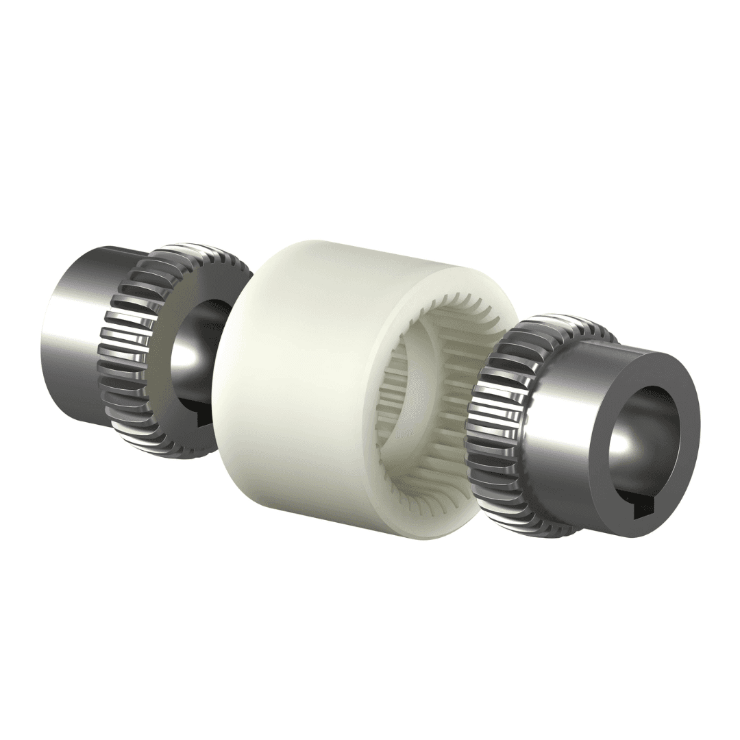
Step 1: Calculate the Base Torque of Your Application
Start with the motor power (kW) and the shaft speed (RPM), using the following equation: T= RPM P×9550 This calculation provides the continuous operating torque that the coupling must be capable of transmitting under normal operating conditions, before accounting for startup peaks, shock loads, or other transient conditions.
Step 2: Apply the Service Factor
Multiply the base torque by the service factor appropriate for your application's load conditions. A conveyor with a uniform load typically requires a lower service factor, while equipment such as mills or crushers, which experience frequent shock loads, generally requires a higher service factor, typically ranging from 1.5 to 2.5 times the base torque. The resulting value is the design torque, which should be used to select a coupling with sufficient capacity to operate reliably under both normal and peak loading conditions.
Step 3: Verify the Maximum Allowable Speed
Every coupling has a maximum allowable operating speed (RPM), which often decreases as the coupling size increases due to dynamic balancing limitations. Verify that your system's operating speed falls within the maximum RPM rating specified by the manufacturer for the selected coupling size.
Step 4: Confirm the Available Bore Size
The maximum bore diameter available for the selected coupling size must be equal to or greater than the diameter of your shafts. If the shaft diameter exceeds the maximum bore capacity of the coupling selected based on torque, you must move up to the next coupling size, even if the calculated torque does not require it. This ensures the hubs can be properly machined and safely mounted on the shafts.
Step 5: Verify the Expected Shaft Misalignment
Review the angular, parallel, and axial misalignment that the selected coupling is designed to accommodate, and compare those limits with the actual misalignment expected in your installation. If the expected misalignment exceeds the coupling's allowable range, select a coupling with greater misalignment capacity, such as a grid coupling or a gear coupling, even if the torque requirements alone would not require it.