

Couplings for Gearmotors: How to Size Them
The output coupling of a gearmotor operates at higher torque and lower speeds than a direct-drive motor. Proper sizing is essential to prevent costly failures.
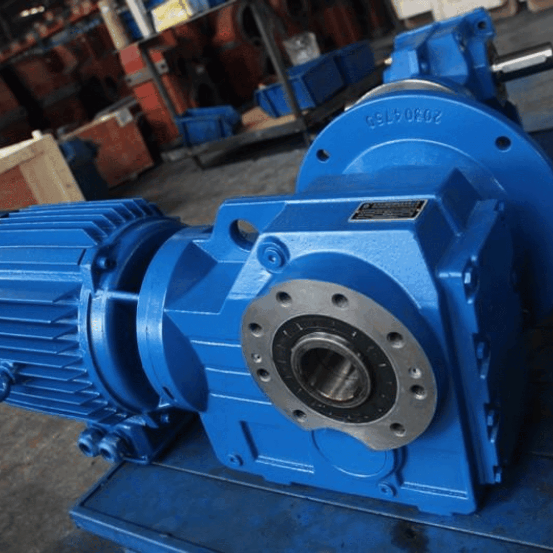
Key Difference Compared to a Direct-Drive Motor
A gearmotor delivers higher torque and lower speed at its output shaft compared to a direct-drive motor. This means the coupling connecting the gearmotor output to the driven equipment must be sized based on the torque already multiplied by the gear reduction ratio, not on the original motor's rated torque.
Steps to Size the Coupling
Use the gearmotor output torque, as specified by the manufacturer on the nameplate or in the technical datasheet, rather than the input motor torque. Apply the service factor according to the type of load driven by the equipment, just as you would for any other coupling selection. Verify the output shaft diameter of the gearmotor, which is typically larger than that of a direct-drive motor, and confirm that the coupling bore can accommodate it. Consider the output speed, which is generally lower in gearmotors, allowing for a wider range of coupling types with respect to their maximum RPM rating.
Most Common Coupling Types Used with Gearmotors
For low- to medium-power gearmotors driving pumps, mixers, or light-duty conveyors, a jaw coupling with a Hytrel elastomer is typically sufficient. For higher-power gearmotors used in continuous-process applications, a grid coupling or gear coupling with a greater torque margin is recommended.